Application of the Momentum Equation
In this section we will consider the following examples:
- Force due to the flow of fluid round a pipe bend.
- Force on a nozzle at the outlet of a pipe.
- Impact of a jet on a plane surface.
- Force due to flow round a curved vane.
- A curved vane on a Pelton wheel turbine.
- Impact of a jet on An angled plane surface.
1. The force due the flow around a pipe bend
Consider a pipe bend with a constant cross section lying in the
horizontal plane and turning through an angle of  .
.
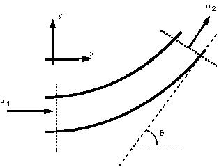
Flow round a pipe bend of constant cross-section
Why do we want to know the forces here? Because the fluid changes
direction, a force (very large in the case of water supply pipes,)
will act in the bend. If the bend is not fixed it will move and
eventually break at the joints. We need to know how much force
a support (thrust block) must withstand.
Step in Analysis:
- Draw a control volume
- Decide on co-ordinate axis system
- Calculate the total force
- Calculate the pressure force
- Calculate the body force
- Calculate the resultant force
1 Control Volume
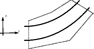
The control volume is draw in the above figure, with faces at
the inlet and outlet of the bend and encompassing the pipe walls.
2 Co-ordinate axis system
It is convenient to choose the co-ordinate axis so that one is
pointing in the direction of the inlet velocity. In the above
figure the x-axis points in the direction of the inlet velocity.
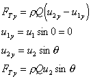
3 Calculate the total force
In the x-direction:
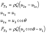
In the y-direction:
4 Calculate the pressure force

5 Calculate the body force
There are no body forces in the x or y directions. The only body
force is that exerted by gravity (which acts into the paper in
this example - a direction we do not need to consider).
6 Calculate the resultant force


And the resultant force on the fluid is given by
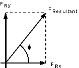

And the direction of application is

the force on the bend is the same magnitude but in the opposite direction

2. Force on a pipe nozzle
Force on the nozzle at the outlet of a pipe. Because the fluid is contracted at the nozzle forces are induced in the nozzle. Anything holding the nozzle (e.g. a fireman) must be strong enough to withstand these forces.
The analysis takes the same procedure as above:
- Draw a control volume
- Decide on co-ordinate axis system
- Calculate the total force
- Calculate the pressure force
- Calculate the body force
- Calculate the resultant force
1 & 2 Control volume and Co-ordinate axis are shown in the figure below.
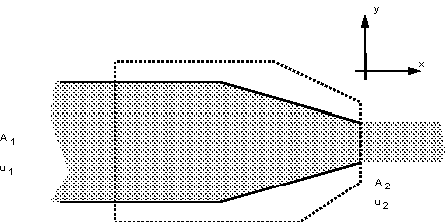
Notice how this is a one dimensional system which greatly simplifies
matters.
3 Calculate the total force

By continuity,  , so
, so

4 Calculate the pressure force

We use the Bernoulli equation to calculate the pressure

Is friction losses are neglected, 
the nozzle is horizontal, 
and the pressure outside is atmospheric, ,
,
and with continuity gives

5 Calculate the body force
The only body force is the weight due to gravity in the y-direction
- but we need not consider this as the only forces we are considering
are in the x-direction.
6 Calculate the resultant force


So the fireman must be able to resist the force of

3. Impact of a Jet on a Plane
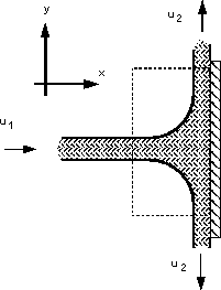
We will first consider a jet hitting a flat plate (a plane) at an angle of 90, as shown in the figure below.
We want to find the reaction force of the plate i.e. the force the plate will have to apply to stay in the same position.
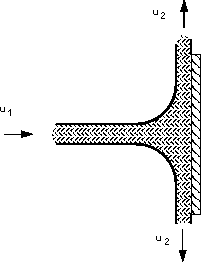
A perpendicular jet hitting a plane.
The analysis take the same procedure as above:
- Draw a control volume
- Decide on co-ordinate axis system
- Calculate the total force
- Calculate the pressure force
- Calculate the body force
- Calculate the resultant force
1 & 2 Control volume and Co-ordinate axis are shown in the figure below.
3 Calculate the total force

As the system is symmetrical the forces in the y-direction cancel i.e.

4 Calculate the pressure force.
The pressure force is zero as the pressure at both the inlet and
the outlets to the control volume are atmospheric.
5 Calculate the body force
As the control volume is small we can ignore the body force due
to the weight of gravity.
6 Calculate the resultant force

Exerted on the fluid.
The force on the plane is the same magnitude but in the opposite direction

4. Force on a curved vane
This case is similar to that of a pipe, but the analysis is simpler because the pressures are equal - atmospheric , and both the cross-section and velocities (in the direction of flow) remain constant. The jet, vane and co-ordinate direction are arranged as in the figure below.
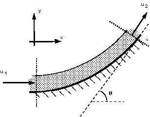
Jet deflected by a curved vane.
1 & 2 Control volume and Co-ordinate axis are shown in
the figure above.
3 Calculate the total force in the x direction

but  , so
, so

and in the y-direction

4 Calculate the pressure force.
Again, the pressure force is zero as the pressure at both the
inlet and the outlets to the control volume are atmospheric.
5 Calculate the body force
No body forces in the x-direction,  = 0.
= 0.
In the y-direction the body force acting is the weight of the fluid. If V is the volume of the fluid on he vane then,

(This is often small is the jet volume is small and sometimes ignored in analysis.)
6 Calculate the resultant force


And the resultant force on the fluid is given by

And the direction of application is

exerted on the fluid.
The force on the vane is the same magnitude but in the opposite direction

5. Pelton wheel blade
The above analysis of impact of jets on vanes can be extended and applied to analysis of turbine blades. One particularly clear demonstration of this is with the blade of a turbine called the pelton wheel. The arrangement of a pelton wheel is shown in the figure below. A narrow jet (usually of water) is fired at blades which stick out around the periphery of a large metal disk. The shape of each of these blade is such that as the jet hits the blade it splits in two (see figure below) with half the water diverted to one side and the other to the other. This splitting of the jet is beneficial to the turbine mounting - it causes equal and opposite forces (hence a sum of zero) on the bearings.
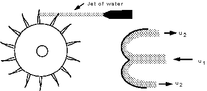
Pelton wheel arrangement and jet hitting cross-section
of blade.
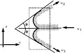
A closer view of the blade and control volume used for analysis can be seen in the figure below.
Analysis again take the following steps:
- Draw a control volume
- Decide on co-ordinate axis system
- Calculate the total force
- Calculate the pressure force
- Calculate the body force
- Calculate the resultant force
1 & 2 Control volume and Co-ordinate axis are shown in
the figure below.
3 Calculate the total force in the x direction
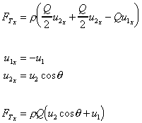
and in the y-direction it is symmetrical, so

4 Calculate the pressure force.
The pressure force is zero as the pressure at both the inlet and
the outlets to the control volume are atmospheric.
5 Calculate the body force
We are only considering the horizontal plane in which there are
no body forces.
6 Calculate the resultant force

exerted on the fluid.
The force on the blade is the same magnitude but in the opposite direction

So the blade moved in the x-direction.
In a real situation the blade is moving. The analysis can be extended to include this by including the amount of momentum entering the control volume over the time the blade remains there. This will be covered in the level 2 module next year.
6. Force due to a jet hitting an inclined plane
We have seen above the forces involved when a jet hits a plane
at right angles. If the plane is tilted to an angle the analysis
becomes a little more involved. This is demonstrated below.
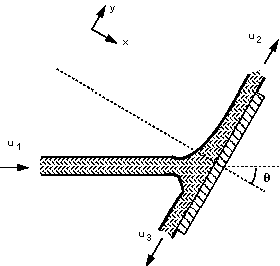
A jet hitting an inclined plane.
(Note that for simplicity gravity and friction will be neglected
from this analysis.)
We want to find the reaction force normal to the plate so we choose the axis system as above so that is normal to the plane. The diagram may be rotated to align it with these axes and help comprehension, as shown below
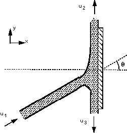
Rotated view of the jet hitting the inclined plane.
We do not know the velocities of flow in each direction. To find these we can apply Bernoulli equation

The height differences are negligible i.e. z1 = z2 = z3 and the pressures are all atmospheric = 0. So
. u1 = u2 = u3 = u
By continuity
Q1 = Q2 + Q3
u1A1 = u2A2 + u3A3
so
A1 = A2 + A3
Q1 = A1u
Q2 = A2u
Q3 = (A1 - A2)u
Using this we can calculate the forces in the same way as before.
- Calculate the total force
- Calculate the pressure force
- Calculate the body force
- Calculate the resultant force
1 Calculate the total force in the x-direction.
Remember that the co-ordinate system is normal to the plate.

but  as the jets are parallel to the plate
with no component in the x-direction.
 , so
, so

2. Calculate the pressure force
All zero as the pressure is everywhere atmospheric.
- Calculate the body force
As the control volume is small, hence the weight of fluid is small,
we can ignore the body forces.
4. Calculate the resultant force

exerted on the fluid.
The force on the plate is the same magnitude but in the opposite direction

We can find out how much discharge goes along in each direction
on the plate. Along the plate, in the y-direction, the total force
must be zero,  .
.
Also in the y-direction:  , so
, so

As forces parallel to the plate are zero,

From above 

and from above we have  so
so
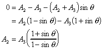
as u2 = u3 = u


So we know the discharge in each direction
