Applications of the Bernoulli Equation
The Bernoulli equation can be applied to a great many situations not just the pipe flow we have been considering up to now. In the following sections we will see some examples of its application to flow measurement from tanks, within pipes as well as in open channels.
If a stream of uniform velocity flows into a blunt body, the stream lines take a pattern similar to this:
Note how some move to the left and some to the right. But one, in the centre, goes to the tip of the blunt body and stops. It stops because at this point the velocity is zero - the fluid does not move at this one point. This point is known as the stagnation point.
From the Bernoulli equation we can calculate the pressure at this point. Apply Bernoulli along the central streamline from a point upstream where the velocity is u1 and the pressure p1 to the stagnation point of the blunt body where the velocity is zero, u2 = 0. Also z1 = z2.
This increase in pressure which bring the fluid to rest is called the dynamic pressure.
Dynamic pressure = 
or converting this to head (using  )
)
Dynamic head = 
The total pressure is know as the stagnation pressure (or total pressure)
Stagnation pressure = 
or in terms of head
Stagnation head = 
The blunt body stopping the fluid does not have to be a solid. I could be a static column of fluid. Two piezometers, one as normal and one as a Pitot tube within the pipe can be used in an arrangement shown below to measure velocity of flow.
Using the above theory, we have the equation for p2 ,
We now have an expression for velocity obtained from two pressure measurements and the application of the Bernoulli equation.
The necessity of two piezometers and thus two readings make this arrangement a little awkward. Connecting the piezometers to a manometer would simplify things but there are still two tubes. The Pitot static tube combines the tubes and they can then be easily connected to a manometer. A Pitot static tube is shown below. The holes on the side of the tube connect to one side of a manometer and register the static head, (h1), while the central hole is connected to the other side of the manometer to register, as before, the stagnation head (h2).
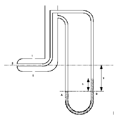
Consider the pressures on the level of the centre line of the Pitot tube and using the theory of the manometer,
We know that  , substituting this in to
the above gives
, substituting this in to
the above gives
The Pitot/Pitot-static tubes give velocities at points in the flow. It does not give the overall discharge of the stream, which is often what is wanted. It also has the drawback that it is liable to block easily, particularly if there is significant debris in the flow.
The Venturi meter is a device for measuring discharge in a pipe. It consists of a rapidly converging section which increases the velocity of flow and hence reduces the pressure. It then returns to the original dimensions of the pipe by a gently diverging 'diffuser' section. By measuring the pressure differences the discharge can be calculated. This is a particularly accurate method of flow measurement as energy loss are very small.
Applying Bernoulli along the streamline from point 1 to point 2 in the narrow throat of the Venturi meter we have
By the using the continuity equation we can eliminate the velocity u2,
Substituting this into and rearranging the Bernoulli equation we get
To get the theoretical discharge this is multiplied by the area. To get the actual discharge taking in to account the losses due to friction, we include a coefficient of discharge
This can also be expressed in terms of the manometer readings
Thus the discharge can be expressed in terms of the manometer reading::
Notice how this expression does not include any terms for the elevation or orientation (z1 or z2) of the Venturimeter. This means that the meter can be at any convenient angle to function.
The purpose of the diffuser in a Venturi meter is to assure gradual and steady deceleration after the throat. This is designed to ensure that the pressure rises again to something near to the original value before the Venturi meter. The angle of the diffuser is usually between 6 and 8 degrees. Wider than this and the flow might separate from the walls resulting in increased friction and energy and pressure loss. If the angle is less than this the meter becomes very long and pressure losses again become significant. The efficiency of the diffuser of increasing pressure back to the original is rarely greater than 80%.
4. Flow Through A
Small Orifice
We are to consider the flow from a tank through a hole in the side close to the base. The general arrangement and a close up of the hole and streamlines are shown in the figure below

The shape of the holes edges are as they are (sharp) to minimise frictional losses by minimising the contact between the hole and the liquid - the only contact is the very edge.
Looking at the streamlines you can see how they contract after the orifice to a minimum value when they all become parallel, at this point, the velocity and pressure are uniform across the jet. This convergence is called the vena contracta. (From the Latin 'contracted vein'). It is necessary to know the amount of contraction to allow us to calculate the flow.
We can predict the velocity at the orifice using the Bernoulli equation. Apply it along the streamline joining point 1 on the surface to point 2 at the centre of the orifice.
At the surface velocity is negligible (u1 = 0) and the pressure atmospheric (p1 = 0).At the orifice the jet is open to the air so again the pressure is atmospheric (p2 = 0). If we take the datum line through the orifice then z1 = h and z2 =0, leaving

This is the theoretical value of velocity. Unfortunately it will be an over estimate of the real velocity because friction losses have not been taken into account. To incorporate friction we use the coefficient of velocity to correct the theoretical velocity,
Each orifice has its own coefficient of velocity, they usually lie in the range( 0.97 - 0.99)
To calculate the discharge through the orifice we multiply the area of the jet by the velocity. The actual area of the jet is the area of the vena contracta not the area of the orifice. We obtain this area by using a coefficient of contraction for the orifice
So the discharge through the orifice is given by
Where Cd is the coefficient of discharge, and Cd = Cc Cv
We now have an expression for the discharge out of a tank based on the height of water above the orifice. It would be useful to know how long it would take for the tank to empty.
As the tank empties, so the level of water will fall. We can get an expression for the time it takes to fall by integrating the expression for flow between the initial and final levels.
The tank has a cross sectional area of A. In a time dt the level falls by dh or the flow out of the tank is

(-ve sign as dh is falling)
Rearranging and substituting the expression for Q through the orifice gives
This can be integrated between the initial level, h1, and final level, h2, to give an expression for the time it takes to fall this distance
We have two tanks next to each other (or one tank separated by a dividing wall) and fluid is to flow between them through a submerged orifice. Although difficult to see, careful measurement of the flow indicates that the submerged jet flow behaves in a similar way to the jet in air in that it forms a vena contracta below the surface. To determine the velocity at the jet we first use the Bernoulli equation to give us the ideal velocity. Applying Bernoulli from point 1 on the surface of the deeper tank to point 2 at the centre of the orifice, gives
i.e. the ideal velocity of the jet through the submerged orifice depends on the difference in head across the orifice. And the discharge is given by
6. Time for Equalisation
of Levels in Two Tanks
By a similar analysis used to find the time for a level drop in a tank we can derive an expression for the change in levels when there is flow between two connected tanks.
Applying the continuity equation
Also we can write 
So
Then we get
Re arranging and integrating between the two levels we get
(remember that h in this expression is the difference in height between the two levels (h2 - h1) to get the time for the levels to equal use hinitial = h1 and hfinal = 0).
Thus we have an expression giving the time it will take for the two levels to equal.
A notch is an opening in the side of a tank or reservoir which extends above the surface of the liquid. It is usually a device for measuring discharge. A weir is a notch on a larger scale - usually found in rivers. It may be sharp crested but also may have a substantial width in the direction of flow - it is used as both a flow measuring device and a device to raise water levels.
We will assume that the velocity of the fluid approaching the weir is small so that kinetic energy can be neglected. We will also assume that the velocity through any elemental strip depends only on the depth below the free surface. These are acceptable assumptions for tanks with notches or reservoirs with weirs, but for flows where the velocity approaching the weir is substantial the kinetic energy must be taken into account (e.g. a fast moving river).
8. A General Weir Equation
To determine an expression for the theoretical flow through a notch we will consider a horizontal strip of width b and depth h below the free surface, as shown in the figure below.
integrating from the free surface,  , to
the weir crest,
, to
the weir crest,  gives the expression
for the total theoretical discharge
gives the expression
for the total theoretical discharge
This will be different for every differently shaped weir or notch. To make further use of this equation we need an expression relating the width of flow across the weir to the depth below the free surface.
For a rectangular weir the width does not change with depth so there is no relationship between b and depth h. We have the equation,
Substituting this into the general weir equation gives
To calculate the actual discharge we introduce a coefficient of
discharge,  , which accounts for losses
at the edges of the weir and contractions in the area of flow,
giving
, which accounts for losses
at the edges of the weir and contractions in the area of flow,
giving
For the "V" notch weir the relationship between width and depth is dependent on the angle of the "V".
If the angle of the "V" is  then the width, b, a depth h from the free surface
is
then the width, b, a depth h from the free surface
is
So the discharge is
And again, the actual discharge is obtained by introducing a coefficient of discharge